
Planes in Surpac are fundamental tools for visualizing and analyzing spatial data. In this detailed article, we’ll break down their role, functionality, and significance in mining and geology while maintaining simplicity for easy understanding. By the end of this guide, you’ll have a comprehensive grasp of planes in Surpac and their various applications.
What Are Planes in Surpac?
In Surpac, planes are defined as “corridors” within a three-dimensional space that help in data visualization. These corridors are established by defining a flat plane (horizontal, vertical, or inclined) and specifying distances toward and away from the plane. The total width of the corridor is the sum of these distances.
When a plane is active, only data within this corridor is displayed, making it easier to focus on specific sections while hiding irrelevant data.
Why Are Planes Important?
Planes serve diverse purposes for geologists, engineers, and surveyors:
- Geologists use them for examining vertical cross-sections of drillholes and surface topography.
- Engineers utilize planes to view horizontal sections of block models, especially during pit design.
- Surveyors create cross-sections of mined areas to analyze cuts over specified periods.
Understanding the “Active Plane”
The active plane is the current reference plane in Surpac. It determines where data is projected in the Graphics view. Here’s how it works:
- If no plane is chosen, a default horizontal plane at zero elevation with a 10,000-meter projection distance (above and below) becomes active.
- Data outside the defined corridor is hidden from view, making it easier to work within specific zones.
- The location of digitized points aligns with the intersection of the active plane and where you click in the Graphics view.
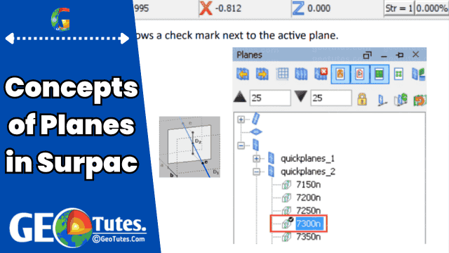
To identify the active plane, users can check the Status Bar or the Planes Panel.
Types of Planes in Surpac
- Horizontal Planes
Useful for analyzing block models or viewing flat topographic surfaces. - Vertical Planes
Commonly employed in geological studies to inspect drillhole cross-sections. - Inclined Planes
Designed for scenarios where neither horizontal nor vertical planes fit, such as analyzing inclined ore bodies.
Key Features of Planes in Surpac
1. Planes Panel
The Planes Panel in Surpac is a user interface element that helps manage plane settings. By default, it is located in the upper-right corner of the Graphics window and can be relocated for convenience.
2. Projection Distances
Projection distances define the thickness of a plane’s corridor. The total thickness is calculated as the sum of the “towards” and “away” projection distances. Users can adjust these settings to include or exclude specific data.
3. Storage Options
Planes can be stored either temporarily or permanently:
- Temporary Storage: Planes are removed once Surpac is closed.
- Permanent Storage: Stored planes are saved in files and remain available for future use.
4. Groups of Planes
Planes can be grouped into collections based on their orientation (horizontal, vertical, inclined). These groups can be managed and edited collectively or individually using the Parameter Set Editor.
Viewing Modes for Planes in Surpac
Surpac offers two viewing modes for data visualization:
- 2D Mode: Projects all data onto the active plane, ideal for focused cross-sectional views. Users can zoom and pan but cannot rotate data in this mode.
- 3D Mode: Provides a full three-dimensional view, allowing for rotation, zooming, and panning to explore data from different angles.
Customizing and Managing Planes
Accessing Plane Properties
Users can view and edit the properties of individual or grouped planes. For instance:
- Adjusting projection distances.
- Renaming or relocating planes within folders.
Dynamic Plane
If an active plane lacks a name, it is termed the Dynamic Plane. This default setting ensures continuous interaction with data during visualization or digitization.
Practical Applications of Planes in Surpac
- Mining Operations
- Creating pit designs by viewing horizontal slices of a block model.
- Analyzing ore distribution within specific layers.
- Geological Studies
- Investigating subsurface structures using vertical and inclined cross-sections.
- Surveying
- Visualizing mined areas and cut depths over time to monitor progress.
Enhancing Workflows with Planes in Surpac
By mastering the concepts of planes, users can achieve:
- Better Data Management: Focusing on relevant data while hiding distractions.
- Improved Analysis: Customizing projection distances to suit specific tasks.
- Seamless Collaboration: Sharing stored planes among team members for consistent project outcomes.
Final Thoughts on Planes in Surpac
Planes in Surpac are essential for efficient data visualization and analysis in geological and mining applications. Whether you’re a geologist exploring drillhole data, an engineer designing a pit, or a surveyor monitoring mining cuts, understanding how to use planes can significantly enhance your workflow